20+ use case diagram sysml
A use case diagram is a graphical depiction of a users possible interactions with a system. Well now draw the first process.

Complete Use Case Model Level 3 Download Scientific Diagram
By drawing a Data Flow Diagram you can tell the information provided by and delivered to someone who takes part in system processes the information needed to complete the processes and the information needed to be stored and.
. 139 Modeling Structural Flow Allocation. What is StarUML used for. Abstract complexity visually using industry standard languages UML SysML AUTOSAR DoDAF MODAF UPDM validate functionality early in development and automate delivery of innovative high quality products.
Use case diagram. Data Flow Diagram DFD provides a visual representation of the flow of information ie. Download Samplezip of this tutorial and extract the zip file to any directory.
SysML has strict syntax and rules for relationships and connections between elements which helps to avoid ambiguity. The reader can assume that unless otherwise specified when I refer to MBSE I mean MBSE with SysML. The actors are often shown as stick.
A use case diagram shows various use cases and different types of users the system has and will often be accompanied by other types of diagrams as well. Name the new process System. The individual outcome of such efforts an engineered system can be defined as a.
2002-06-20 2020-07-23 v162 No Commercial Free Community Edition Java C Windchill Modeler. 01212022 Create an account. State Machine Diagram SysML 15 Use Case Diagram SysML 15 Request Symbols.
It supports the specification analysis design verification and validation of a broad range of systems and systems-of-systems. Enter Context as diagram name and click OK to confirm. Data within a system.
The secondary challenge is to optimize the allocation of necessary inputs and apply. The diagramming modules are optimized for. In the New Diagram window select Data Flow Diagram and click Next.
Other than Java it also generates code for C C PHP5 and PHP4. The same applies if you are working on more than three active documents at the same time. Communication diagrams used to be called collaboration diagrams in UML 1xThey describe interactions between objects and parts using sequenced messages.
See how a class diagram in UML is defined examine a class diagram example view symbols and notation and discover the importance of class diagrams. Subsequently the Object Management Group OMG adopted a version of SysML as. UCDUse Case Diagram用例图.
Work with same UX in multiple platforms including macOS Windows and Linux. Study the source code. MathWorks Simulink Simulink is a block diagram environment for.
A diagram is a partial graphic representation of a systems model. Next lets create an external entity. The Systems Modeling Language SysML is a general-purpose modeling language for systems engineering applications.
The set of diagrams need not completely cover the model and deleting a diagram does not change the model. If you want to design complex diagrams with more than 60 objects you need a premium account. SysML was originally developed by an open source specification project and includes an open source license for distribution.
AWS Desktop App Streaming. This UML diagram software allows you to discover and install third-party extensions. This article compares SysML tools.
Allows you to create Obje3ct Use case Deployment Seque3nce Communication Activity and profile Diagram. IDEF initially an abbreviation of ICAM Definition and renamed in 1999 as Integration Definition is a family of modeling languages in the field of systems and software engineeringThey cover a wide range of uses from functional modeling to data simulation object-oriented analysis and design and knowledge acquisition. ConceptDraw DIAGRAM v12 provides robust and comprehensive drawing tools.
PTC Windows 1997 2021 May v94 No Commercial Education C Name. Since the application uses Java Web. StarUML is more than just a diagram modeling tool.
What can Software Ideas Modeler help me with. Create a new project by selecting Project New from the application toolbar. Software Ideas Modeler is an essential tool in software engineeringIt is a feature-rich CASE tool that can help you with software design using various diagram notations and modeling tools.
The model may also contain documentation that drives the model elements and diagrams such as written use cases. Try our UML modeler ERD designer flowchart maker wireframing tools or BPMN editor for free. Read the register method in RegisterControllerjava to see how it works.
ConceptDraw DIAGRAM offers a range of business business-specific add-ons for creating Infographics diagrams data visualization and flowcharts for the business process model. He described how this technique was used at Ericsson to capture and specify requirements of a system using textual structural and visual modeling techniques to drive object oriented analysis and design. Systems engineering is an interdisciplinary field of engineering and engineering management that focuses on how to design integrate and manage complex systems over their life cyclesAt its core systems engineering utilizes systems thinking principles to organize this body of knowledge.
Name Creator Platform OS. Originally he had used the terms usage scenarios and usage. In this and future posts I will use the Systems Modeling Language SysML which is commonly used for system modeling.
2 UML 2 for systems engineering applications in 2003. It supports MDA short for Model Driven Architecture which makes complex coding possibleAimed at experts who use UML extensively the program provides code generators supports plugins and offers an overview of the model before completionFurthermore the application lets users. SysML tools are software applications which support some functions of the Systems Modeling Language.
To create new DFD select Diagram New from the toolbar. In 1987 Ivar Jacobson presented the first article on use cases at the OOPSLA87 conference. UML diagrams represent two different views of a system model.
An item flow can be a common item to both an abstract eg logical internal block diagram and a concrete eg physical internal block diagram. Project management is the process of leading the work of a team to achieve all project goals within the given constraints. No limit for using this commercial software for evaluation.
From the Diagram Toolbar drag Process onto the diagram. Supports a range of diagram options. These diagrams show an instance of a class diagram and its data structure at a specific timeThey represent a static view or snapshot of a system at a particular moment.
Rick Steiner in Practical Guide to SysML 2008. The use cases are represented by either circles or ellipses. ArgoUML offers support for a range of UML 14 diagrams including statechart activity sketches class diagrams use-case diagrams collaboration designs deployment and sequence diagrams among others.
Test case modification and re-execution without re-compilation. UMLSysML modeling enables you to create source code quickly in the IDE for the specified languages C and C and Ada. In the New Project window enter Account Registration as project name and click Create Blank Project.
This information is usually described in project documentation created at the beginning of the development processThe primary constraints are scope time and budget. This enables a common structural data model to be maintained between logical and physical hierarchies.

11 High Level Use Case Diagram For A Sysml Human Model Humansys Download Scientific Diagram

The Use Case Diagram Of The Acc System Download Scientific Diagram
A Sysml Use Case Diagram For The Smart Streetlight Use Case Download Scientific Diagram

Use Case Diagram Example Download Scientific Diagram

Itasat High Level Use Cases To Specify System Requirements 3 Download Scientific Diagram

Use Case Diagram For High Level Use Cases Download Scientific Diagram

Fuel Pump Use Case Diagram Download Scientific Diagram

An Example Use Case Diagram Showing Possible Misuse And Mitigation Download Scientific Diagram

The Use Case Diagram Of The Rice Cooker Controller Download Scientific Diagram

Use Case Diagram Of A Car Navigation System Cns Download Scientific Diagram

Use Case Diagram Level 1 Download Scientific Diagram

Use Case Diagram 4 4 Information Use Case Download Scientific Diagram

Sysml Use Case Diagram Download Scientific Diagram

Uml Use Case Diagram Of The User Interface Pattern Download Scientific Diagram

Use Case Model On Conceptual Design Download Scientific Diagram

Example Of Use Case Diagram Generation K 2 A The Original Opm Download Scientific Diagram
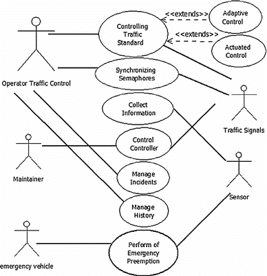
Sysml Use Case Diagram For The Traffic Control System Download Scientific Diagram